Thursday, May 4, 2023

I had the radio on, I was drivin’

The day didnt start with the sun beating down but it did feel great to be back on the road. I left after the morning rush so it wasnt too bad getting through town and had light traffic all the way to Idaho. 

So many previous drives have started off this direction; the usual lunch and gas in Pendleton, first stop in Boise. Lots of familiar sights along the way that make the drive feel so much shorter. The climb up Cabbage Hill was fun as always, and the twisty bits after that, following the Grand Ronde River are always a fun spot before hitting the straighter segments of I-84. 

Tomorrow is the longest drive of the trip at 540 miles but the scenery should start to get more interesting once I am past SLC. 

Stats for today: 
432 miles
~7 hours driving
One fuel stop, averaging 28mpg on the first tank. That dropped a bit after lunch with the mountain passes and higher speeds but still better than I was expecting.

Wednesday, May 3, 2023

Sabbatical !!!

No, not a very loud sabbatical, the third sabbatical. It's been several years since I've done a proper roadtrip and I've been wanting to get back to Utah for quite some time so this seemed like a good opportunity to hit the road. The plan is for about three weeks and 4500 miles covering Oregon, Idaho, Utah, Arizona, New Mexico, Nevada and California. I'll be posting updates and some pictures here, hopefully each night if I have time.
As is tradition I have to at least start out with a clean car, even though the forecast is for rain for most of the drive out of Oregon. Hoping that stays rain and I don't get snow like has happened in past years. So then, it will be awhile before the RS is this clean again.
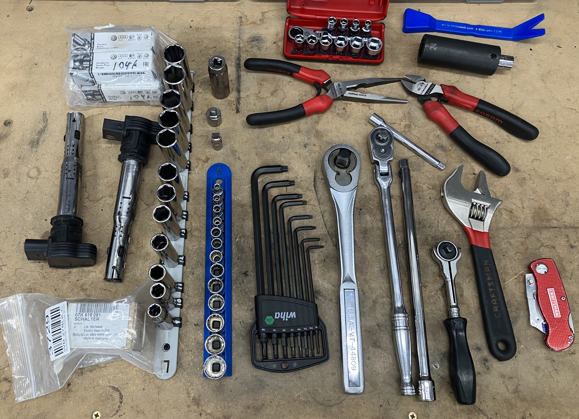
And since it's getting on in years I figured I should pack some tools and spares this time around. Packing many of the same tools as I had for the cross-country trip in the mk1. Spares this time around are the usual spark plugs and coilpacks and an oil pressure sensor, which seems to be this car's version of the MAF from the mk1.

Wednesday, March 13, 2019

A word of caution for folks using C5 RS6 rear rotors, I've had another case of broken lugs

A couple of weeks ago I had another instance of broken lugs on my car. One sheared completely while torquing it, one with hairline cracks and two more that were hanging on by a single thread. The first time this occurred a couple of years ago it was also 3 broken lugs. It's worth noting that another TTRS owner has had the exact same failure, the broken lugs looked identical to mine. Has anyone else seen this problem?

Install history of 034 C5 RS6 rear rotor upgrade on my car:

3-23-2014, 30000 miles, installed 034 C5 RS6 upgrade
4-30-2014, 31000 miles, installed motorsporthardware.com studs
10-6-2016, 56000 miles, discovered multiple sheared studs, replaced with factory lug bolts
3-10-2018, 69000 miles, JHM C5 RS6 rear rotors installed 
2-26-2019, 78000 miles, discovered sheared factory lug bolts

Time and mileage between failures... Note this is just when I noticed the broken lugs, I have no way to verify when they actually broke. The first time seemed to have been broken for some time before discovery given oxidation on the exposed metal. This more recent time only one lug had broken all the way and the metal was cleaner. Two other lugs were hanging on by a single thread and another was showing hairline cracks so I believe I caught it closer to the actual failure point.

873 days, 25k miles between installing C5 RS6 rotor upgrade and discovering broken studs
890 days, 23k miles between replacing studs with bolts and finding broken bolts

This failure has happened with OEM C5 RS6 rotors as well as JHM manufactured C5 RS6 replacement rotors. The failure has occurred with aftermarket studs as well as the factory provided lug bolts. After the first time I assumed it was due to poor quality aftermarket studs but with the factory bolts also shearing I can only presume this is an issue with the fitment of the C5 RS6 rotors on the 8J hubs. In 78000 miles I've never had a single issue with the studs or lug bolts on the front axle.

I tend to be very careful about torquing lugs on my car since my summer Neuspeed wheels require hub-centering rings and I am used to having spacers installed (although never on my TTRS). For those reasons I torque my wheels to ~70ft lb with effectively no weight on the wheel and then follow with a second pass to 90 ft lb. I rarely use an impact gun to remove and never to install. If a shop works on my car and removes the wheels during service I always retorque lugs once I get the car home. I do not believe that any of the lug failures I have had are related to a material defect in the lugs or a result of over torquing.

After examining the differences between the OEM RS6 rotors, the JHM replacements and the Girodisc equivalent (I no longer have my factory TTRS rotors) my theory is that the C5 RS6 hub must be slightly smaller in diameter than the 8J TTRS hub. The TTRS hub comes in contact with either the ridge on the hat (OEM RS6 rotor) or the angled part of the hat (JHM) and in either case the hat does not sit flush against the hub allowing for some movement which over time is compromising the lugs. The Girodisc hat has a flat inner face which should allow it to seat properly across the entire area of the hub surface which I am hoping fixes the problem. I guess I will know for sure in about 880 days.

The JHM rotors seem much worse in fitment but the time and mileage between failures was incredibly similar to the OEM RS6 rotors. Maybe the factory lugs are built to higher spec? In any event I believe the OEM C5 RS6 rotors are not a proper fit for the TTRS and the JHM replacements are potentially even more dangerous.

I've shared all of the above with 034 and they're looking into the issue too but they have only heard of mine and the one other failure.


    Sunday, April 9, 2017

    Oil Drain Access Panel

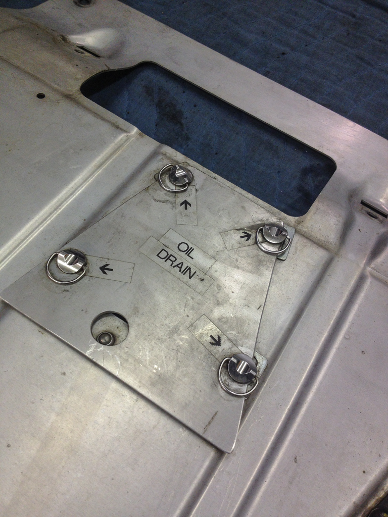
    This was just a quick fun mod I did soon after I got the car to make servicing a bit easier. I stick to a 5k mile oil change interval with filters changed every 10k miles but during track season I'm usually changing just the oil more frequently. The normal procedure for that of course is to remove the 15 or so T25 torx to drop the plastic undertray and then remove the bolts for the aluminum tray. That's all too much work :) Instead I've added a small access panel directly under the oil drain plug and that's attached to the car with quarter-turn fasteners. So for a quick oil drain all I need for tools is the 19mm wrench for the drain plug.

    The quarter turn fasteners were sourced from Pro-Bolt. 14mm D-ring with slide on clips.
    http://www.probolt-usa.com/stainless-steel-qr-studs-s-lide-clips-d-ring-14mm-pack-x-10-mssqrpackslide1014.html

    Some quick pics and measurements for how I did this. You'll note the opening is slightly odd shaped. The original plan was to put a second NACA duct here instead of just a flat cover so that it wouldn't even be noticeable as an access panel. So this panel is quite oversized compared to what's really required.

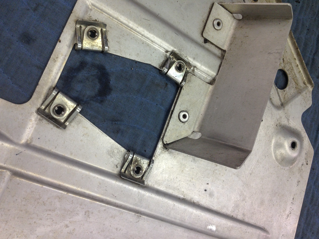
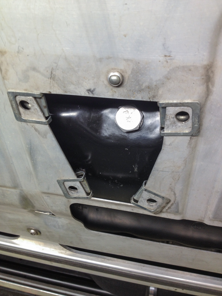
    First a pic of the access hole in the undertray so you can get yourself oriented with where to cut. The left side would be towards the front of the car. There's that big open slot that draw in air that is then deflected up the back side of the engine (note I'd love to build some actual duct work here to direct the air to the turbo area and build a proper chimney, maybe some other day).


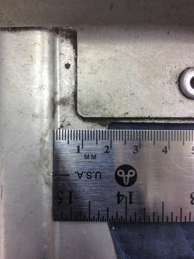
    The oil drain plug is right at the rear edge of the opening, near the deflector, so really you just need to cut an opening from the very edge of the deflector up a few inches. Be careful to leave enough space around the edges for the quarter-turn fasteners. Mine are about 2cm wide.


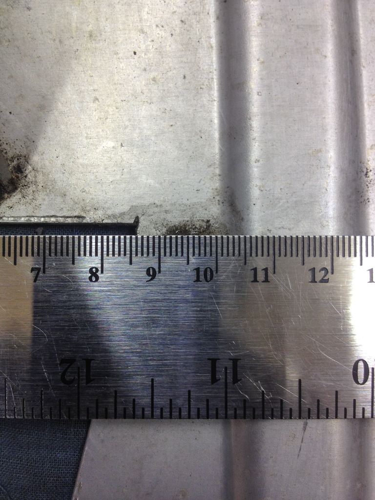
    That leaves a space about 8.5cm wide. Probably wider than needed but nice to have space to swing the wrench.


    And with the cover in place. This is just stock aluminum sheet from the local hardware store and cut to size. I possibly should have left the label maker in the house that day :)
    And again, the sizing was all intended to use a NACA duct for the cover so if you're doing this you can just cut a smaller rectangular opening.

    And finally a picture of the undertray in place showing the available access. This really only works because the TTRS drain plug is at an angle so the flow of oil just misses the back edge of the undertray. Really all that's needed is an 8.5 x 5 cm hole.


    Sunday, February 26, 2017

    Gen4 Haldex Controller


    The installation instructions supplied by Haldex are pretty good, this isn't a very complicated install. However, there were a few tricks I noted as I ended up installing my controller many times (long story) so I thought I would document them here.

    Also, when ordering be sure you order the correct controller for your car. Gen 2 Haldex is physically different from Gen 4 so a Gen 2 controller can not be installed in a Gen 4 coupling.

    Within the Gen 4 family however there are several varieties that are all physically the same but different applications. For a TTRS the Haldex coupling is a 0BY unit and you can order a race or competition controller. TTS, GolfR, Tiguan, Passat, etc all are different coupling variants (0BR, 0AY, etc).

    The usual disclaimers apply... This should only be an hour install at a shop (really more like 15 minutes) so if you're unsure of what your'e doing take it to someone.

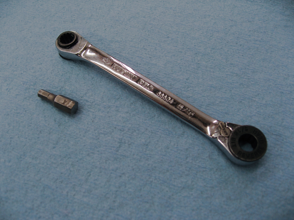
    You don't really need any specialty tools for this installation but there is one that can make life much easier. The top allen bolt is in a tight spot with the fuel tank heat shield just a couple inches away. There's not enough clearance for a 1/4" driver socket on a wrench so one of these small drivers with a 4mm allen bit is perfect.


    Tools:
    4mm allen - 2 bolts securing the controller
    5mm allen - Haldex fill plug in case you need to top it off
    channel locks - Might be required if the throttle valve needs some assistance coming out
    drain pan - You'll lose a small amount of fluid during the swap

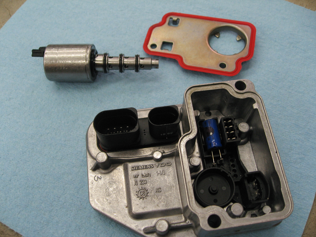
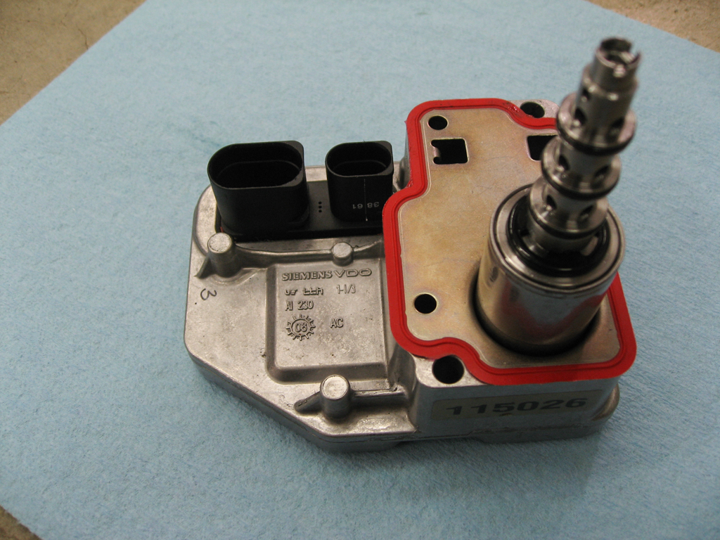
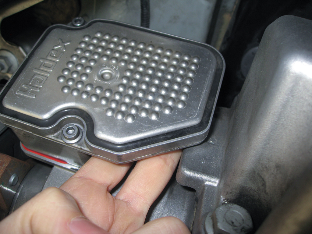
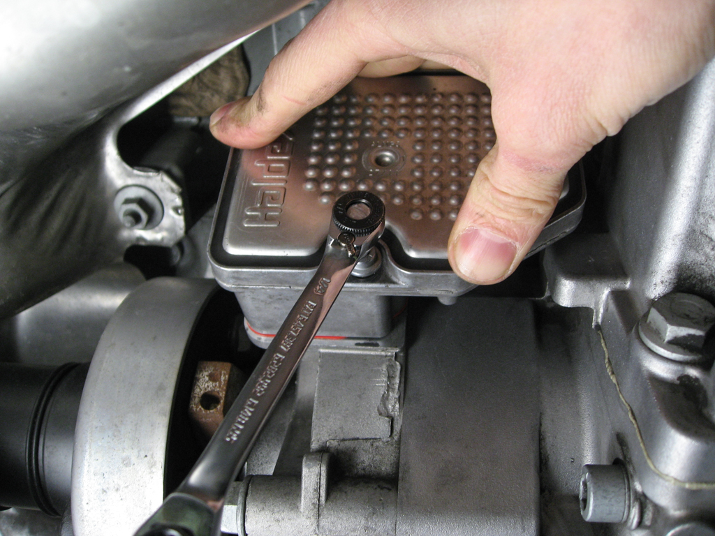
    Here's the main controller unit, the throttle valve and the sealing plate as supplied by Haldex. The stocker controller is all exactly the same as this physically. The second picture shows how everything looks assembled once installed.

    Also, since the parts are identical to the stock controller you may wish to mark the throttle valve with a sharpie so you don't mix them up. I marked mine on the end of the barrel next to the black electrical connector.


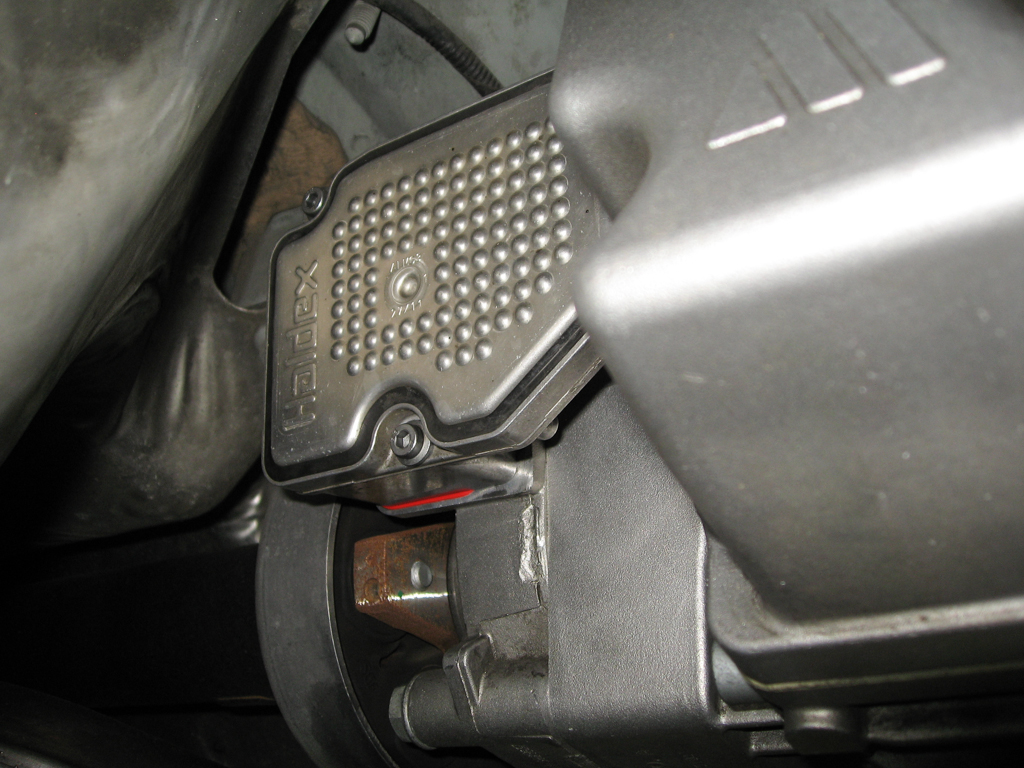
    First find the location of the stock controller :) This is ahead of the rear axle and on the driver side of the car (for LHD cars anyway). You can see the main driveshaft coming in to the coupling in the lower left of the frame.

    Make sure to bring the throttle valve, controller and drain pan before you get started.

    You can just see the red seal peeking out of the bottom of the unit. You'll want to clean around this area a bit before starting so you don't get any dirt/grit/grease into the sealing surface during the swap.


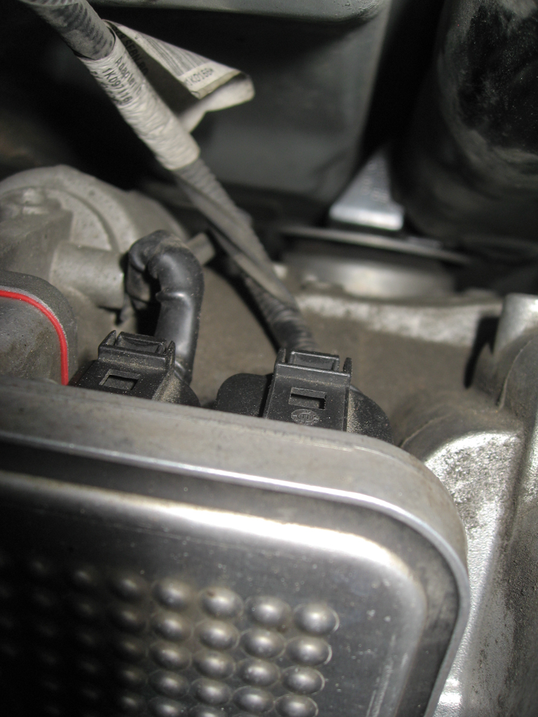
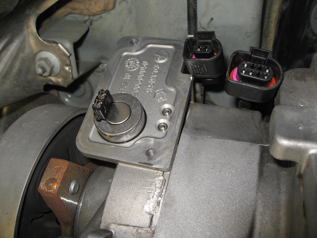
    First step will be to release the electrical connectors at the top of the controller. I had the camera up against the bottom of the car to get this picture... you can't get your head up there so you're working a little blind on this but it's not as bad as it seems. The smaller connector on the left does not have enough slack to come down with the controller but the larger connector on the right does. So if you can't get that one disconnected for whatever reason you can wait.

    You'll note these are standard VAG electrical connectors which have a small tab that must be pushed down/back to release the internal clip. Here's where the first trick comes in.


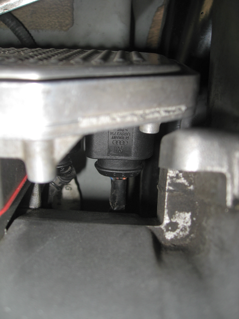
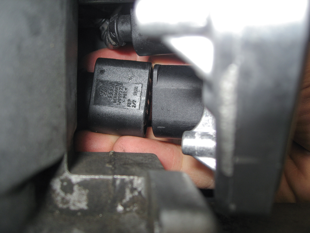
    If you get directly under the controller you'll note that there's a gap between the controller and the coupling itself and you can see the bottom of the two electrical connectors.


    Reach up through the gap and push the connectors forward, as if plugging them in. While holding them that way reach over the top with your other hand and release the clips, you should hear a faint click. If you just reach over the top and push back on the release lever you're also effectively trying to push the plug off at the same time. That puts additional tension on the catch which makes it harder to release.
    By holding the plug still while releasing the clip you take that pressure off.


    Once the two plugs are disconnected it's time to undo the two bolts holding the controller in place. Remove the top bolt first while leaving the lower bolt tight.

    You did remember to bring the new throttle valve with you right? If not get that now :) Also get your drain pan in place under the controller in case there are any leaks as the controller is removed.

    With the top bolt out, use one hand to hold the controller firmly in place while removing the lower bolt.

    There are two reasons to hold the controller in place like this. As noted in the picture above the throttle valve is plugged in to the controller with a fairly small electrical connector so you don't want the weight of the controller hanging off of that connector.

    The second reason is that the Haldex unit may still be under pressure which will cause that throttle valve to pop out as soon as the controller is no longer holding it in place. So hold the controller tight, get the bolt out, and then remove the controller and make sure the throttle valve stays in place.


    Here the controller is removed and the throttle valve is still seated in place. There isn't much of the barrel protruding from the coupling so if it is seated tightly you won't be able to pull it out with just your fingers.

    Do NOT use the electrical connector for leverage... I know you're thinking about it ;)

    If the coupling is still under pressure the throttle valve may just want to pop right out. If the throttle valve is loose then grab the new throttle valve in one hand and pull the old one out and slide the new one in. There is no specific orientation for this to go in, you'll note it spins in place.

    You do need to make sure it it seated fully into the coupling. Press directly on the bottom of the barrel and it should sink another 1/8" into place.

    You'll lose a small amount of fluid during the swap, maybe a tablespoon total. You don't have to be ninja-quick with this but don't do what I did the first time and pull the valve out with the new valve sitting on the workbench :)


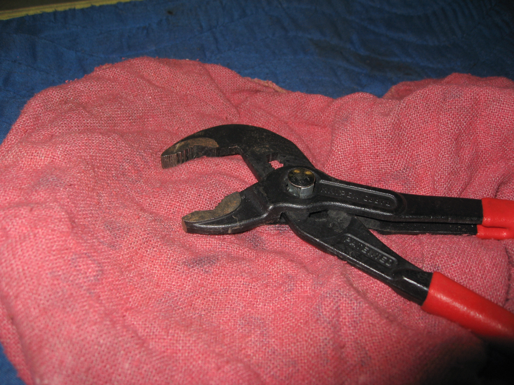
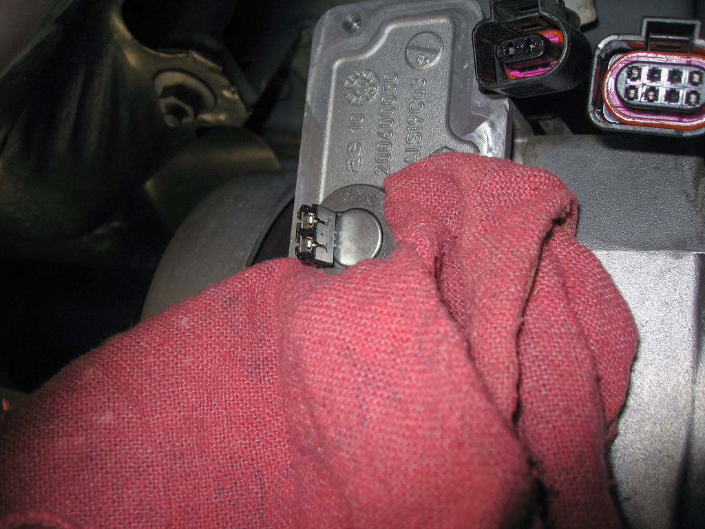
    If the throttle valve does not come out on its own you'll need to add some gentle persuasion. I used a set of channel locks with a shop rag wrapped around the jaws so as to not damage the throttle valve.

    You don't need to use a ton of force to get the throttle valve out and you're not looking to remove it completely using the channel locks. Just use a little leverage to un-seat the valve body, maybe moving it out 1/8".

    Then get the new valve and be ready for the swap. Pop the old one out, slide the new one in. There's no specific orientation for this to be installed, it rotates in place once in. You'll lose a small amount of fluid during the exchange, maybe a tablespoon total.


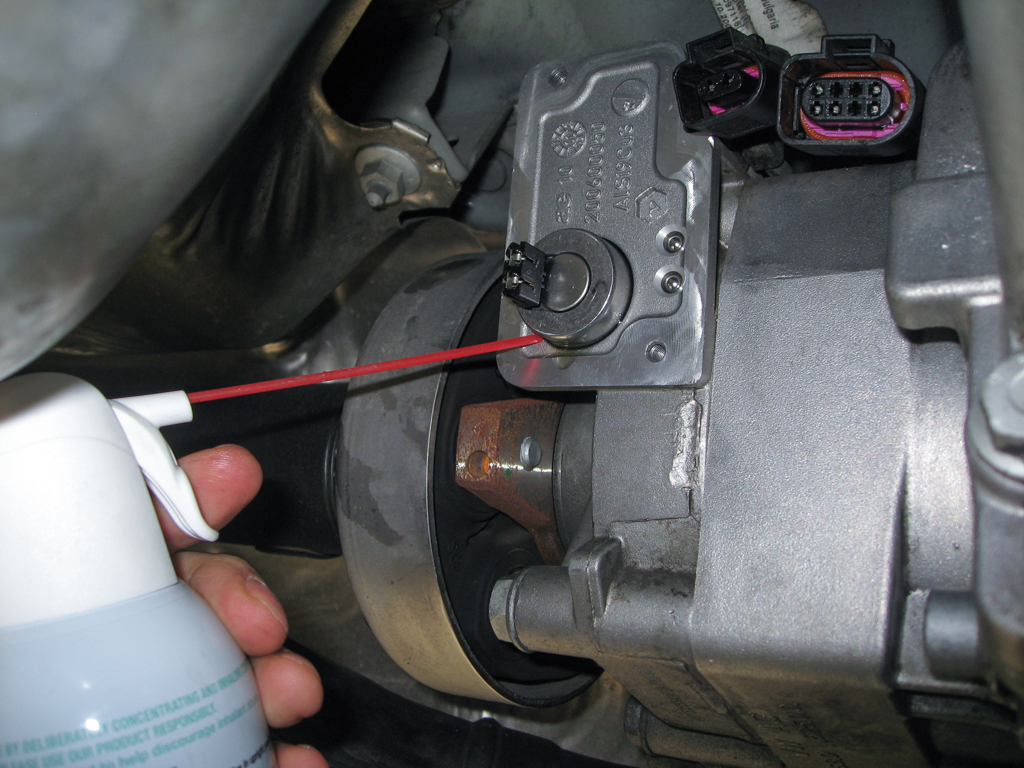
    The barrel of the throttle valve seals deep in the chamber so there will be a small amount of Haldex fluid still running out. I very lightly blew some excess out with a can of compressed air and then wiped down any remaining excess on the outside with a shop rag.

    After cleanup you're ready for reassembly. Note the orientation of the electrical connector on the throttle valve below. That matches the position on the controller. Rotate the throttle valve to this position, bring the controller up level with the valve, don't forget to put the red seal in place!

    Then slowly mate the controller to the throttle valve. This may take a couple of tries, do not force it in and make sure the throttle valve stays correctly oriented. You'll notice that the sealing plate has 4 fingers that hold the throttle valve securely in place so as you tighten the controller those will ensure that the throttle valve is seated 100%.

    Once the controller slides on you can start to thread the lower bolt back into place by hand and then tighten it until it's just about snug but not 100% tight. Then do the top bolt and then go back and tighten both all the way. I noticed that my upper bolt was loose when I started the entire procedure so I reinstalled both with a small amount of medium strength thread locker.


    Reconnect the two electrical connectors. You can look up through the gap to see what you're doing.


    Depending on how much fluid you lost you may need to top off the Haldex fluid. The fill hole is to the right of the controller on the piece with the three large \ marks, sort of looks like an M I guess, just visible on the far right in this picture. It's a 5mm allen socket to remove.


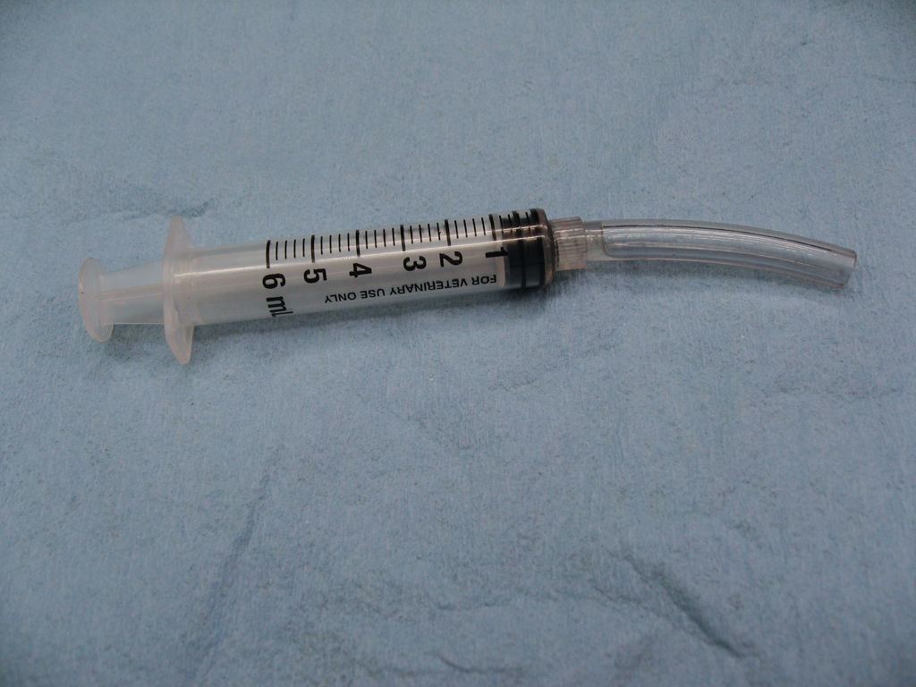
    I used a small syringe with a short length of hose to refill about the same volume that I lost. The part # for the fluid for a Gen4 Haldex coupling is G-060-175-A2.


    That's all there is to it. Double check the allen bolts and electrical connectors are tight and take it for a short test drive. Verify afterwards that there's no fluid leaking from the bottom of the controller.

    Tuesday, March 22, 2016

    Osir TTRS EX side skirt install

    I had been interested in a set of these carbon fiber side skirts for quite some time but I hTad only ever seen one picture of them installed on a car in the wild and there were no install instructions so I had been a bit hesitant. After the 034 intake and MTM rear diffuser I kind of fell off the carbon fiber cliff and decided to go for the skirts and an Osir front splitter to complete the look :)

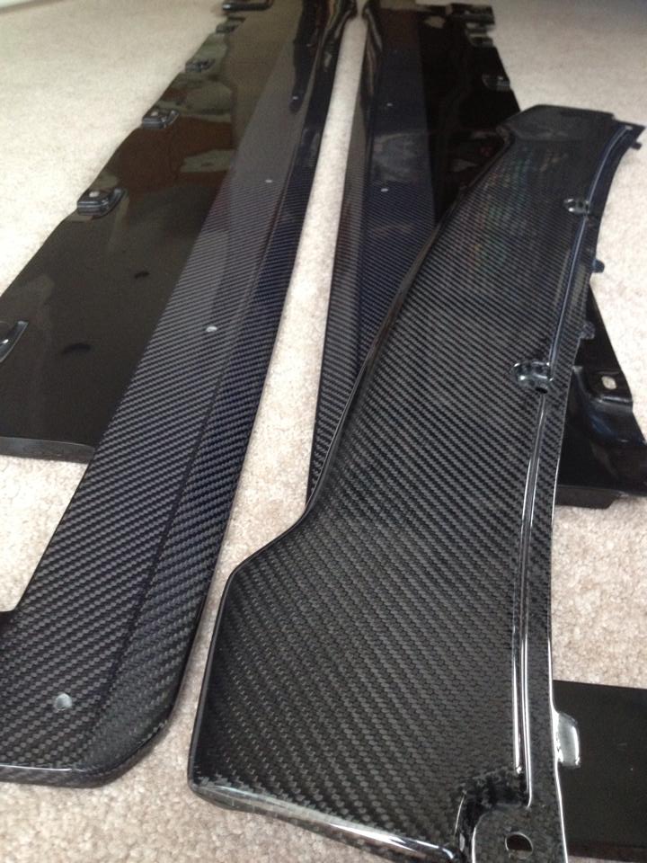
    The skirts themselves are pretty large, about 7ft long and 6-9 inches wide although only about 1/2" thick. They're made of what appears to be a fiberglass and carbon fiber. The fiberglass section is hidden under the bottom of the car and then a lip of carbon fiber extends out along the edge of the factory skirts. It's a subtle effect but the profile suits the lines of the car perfectly. It's a great accent piece.
    Install took about 6hrs but that was making things up as we went since there were no instructions and then the wellnuts fought a bit at the end and that ended up burning quite a bit of time.

    Standard disclaimer. Having large parts of the body fall off while driving down the road, or track, is dangerous. Take it to a bodyshop if you're not sure of what you're doing.
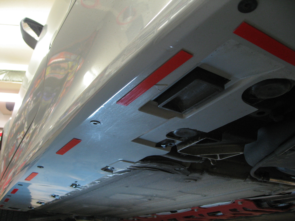

    In the pic below the Osir DF-S splitter is sitting on top of the skirts. The carbon itself is very nice quality with the usual glossy finish. You'll notice too that the fiberglass section has cut-outs to clear the jack pads and if you look closely you'll see raised areas that mate up to the factory skirts. These are very helpful as it gives a fixed location for the skirts to mount to the car. I had been slightly worried that these would have no guides and you'd have to eyeball the fitment but they go exactly where they're supposed to live, no guess work.


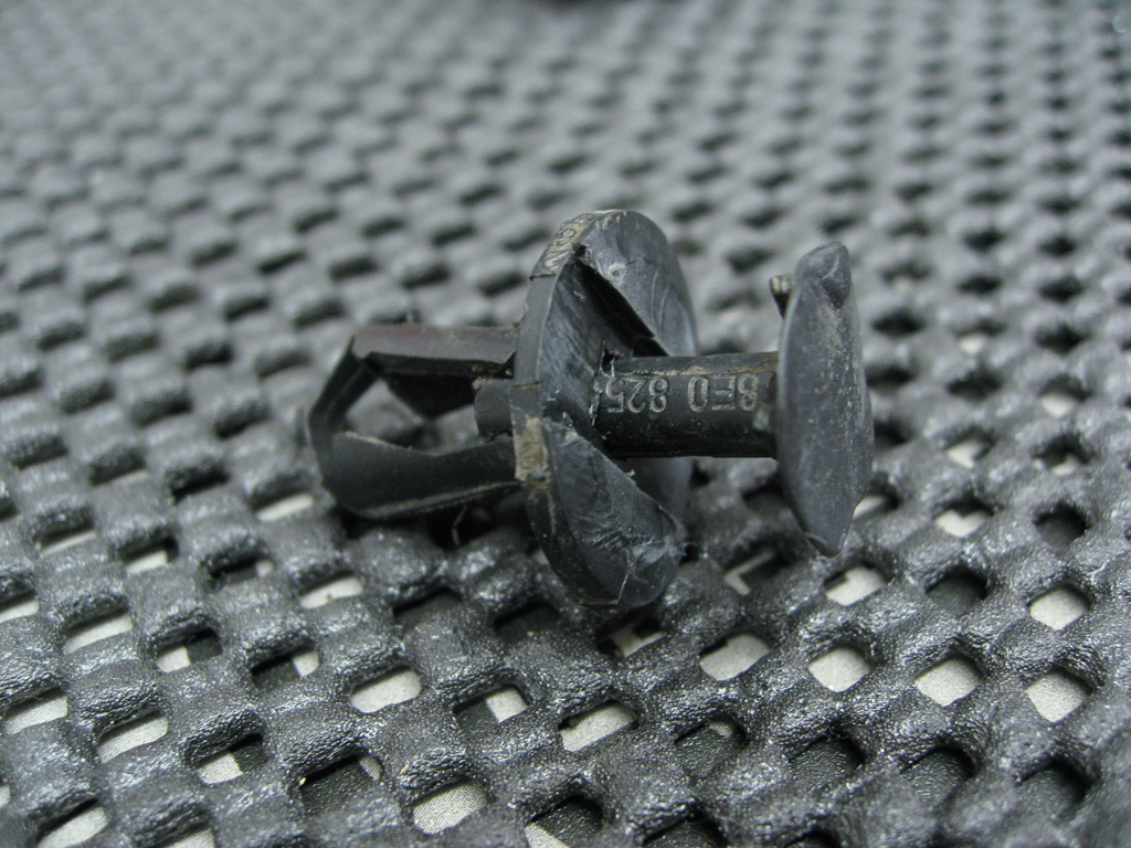
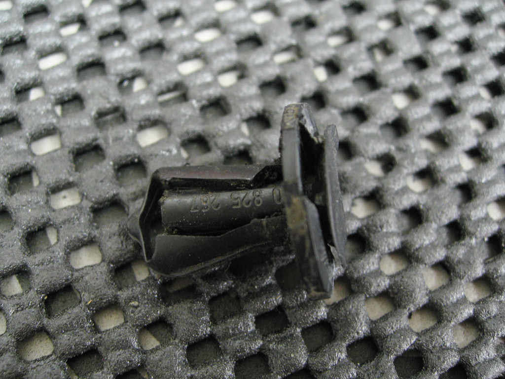
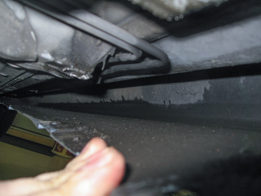
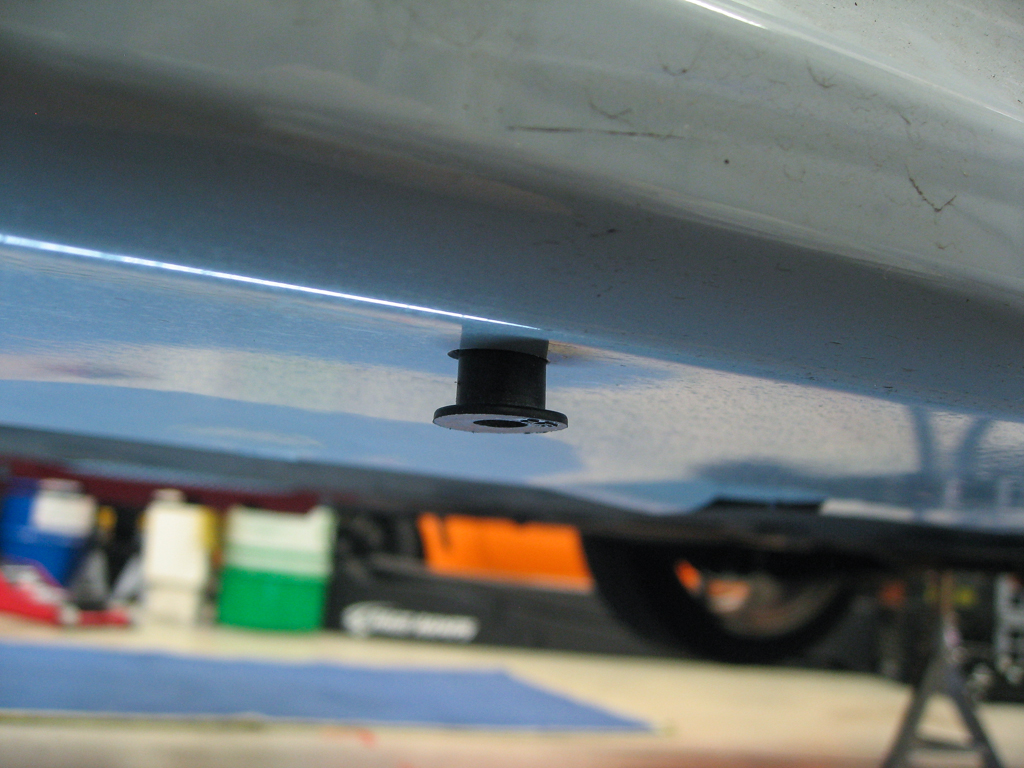
    The factory skirts are attached to the underside of the car using VAG plastic pop rivets. The center rivet portion when seated all the way in pushes the prongs out and that secures the rivet and the bodypart to the unibody.

    These are a different variety than I've used in the past and do not come out very cleanly. The cap portion of them is soft plastic that bends easily. Not much chance of reusing these so just grab onto the center portion with a pair of pliers and yank them out.


    As mentioned there are no installation instructions included but it appears that Osir wants you to use these plastic rivets on the inner row of holes and then use the included wood screws in the outer row of holes to attach the carbon skirts to the factory skirts. IMO that is grossly inadequate.

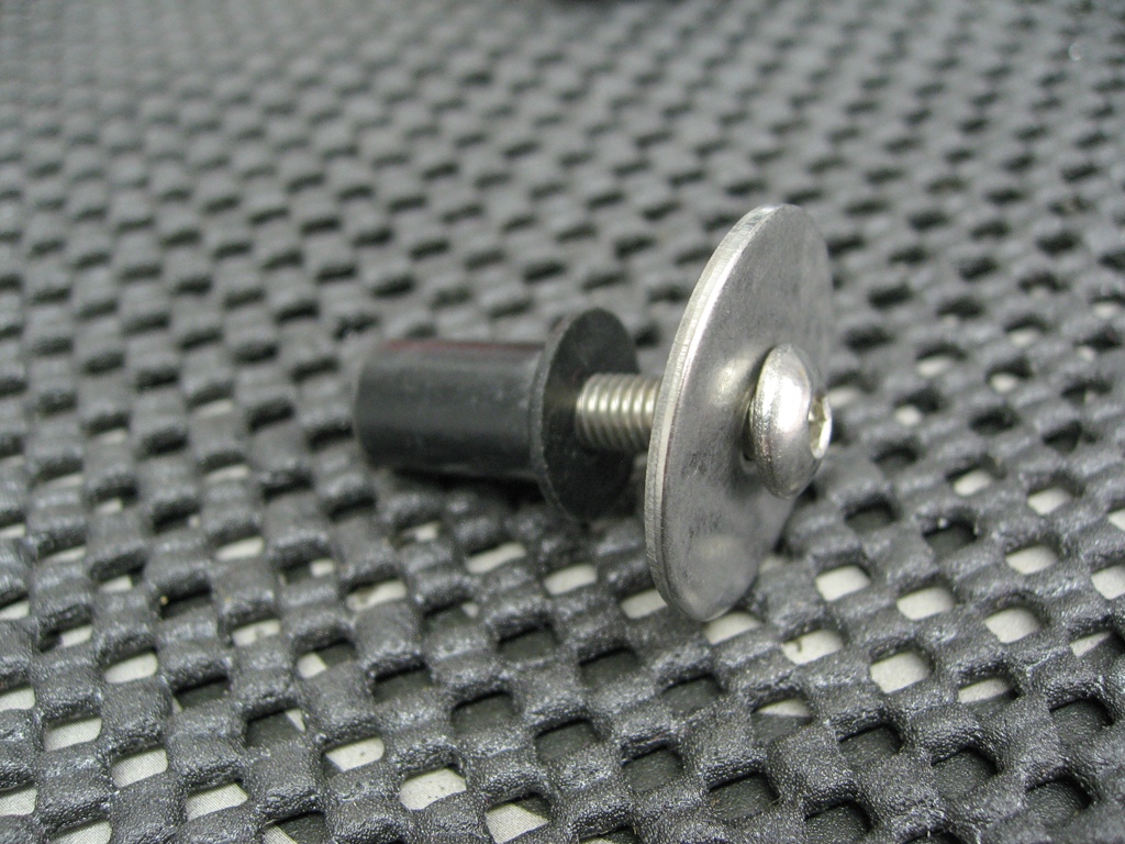
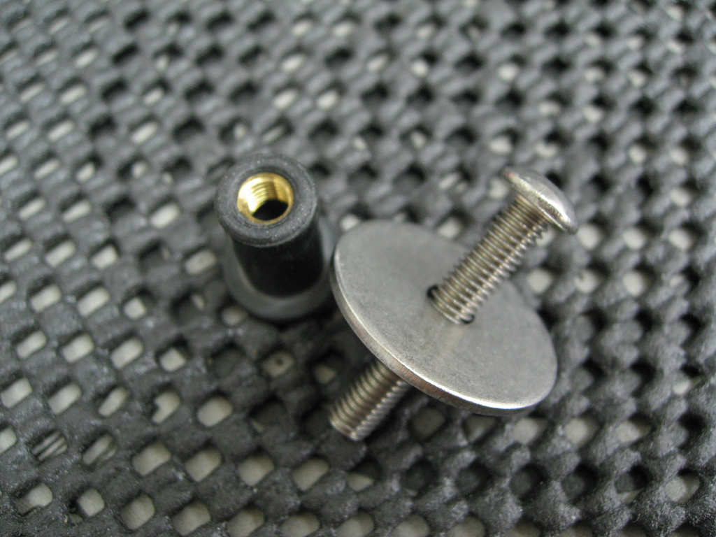
    What I ended up using for both the inner and outer row of fasteners are something called wellnuts. These are a small nut bonded to a rubber sleeve. They are inserted into a hole in the body, similar to a rivet, and then when a bolt is inserted and torqued down the rubber is pulled down and deforms to stay secured in the body. An alternative to this would be rivnuts like I used on the Unibrace install.
    There's 15 per skirt so 30 total and you'll want extras in case you run into problems. The bolts are m5 x 30 and then a fender washer to seat against the Osir skirt.


    Anyway, I felt the wellnuts would be a far more secure way to fasten the Osir skirts to the factory skirts. The inner row of wellnuts would be inserted into the unibody and the outer row would just go into the factory skirts. I was wondering how close the outer edge of the factory skirts (ie the part that is visible under the door) was to the unibody. If it would be possible to drill through the factory skirt and attach a fastener to the unibody for the outer holes. Once you get the plastic rivets out you can pull the factory skirt down from the car and peer inside and it is not anywhere close to the unibody. That's good because there's less chance of accidentally drilling into something important but bad because it limits your options for fasteners. In this case I think using the supplied wood screws would not be very strong since they're just going into 1/8" of ABS. The wellnuts should be much stronger and much more durable.


    To facilitate using the wellnuts for the outer row of fasteners holes needed to be drilled in the factory skirts. In order for the wellnuts to work they need to be very snug in the holes. We used a step-bit and checked the depth and fitment carefully as we went. You also need to mark these precisely since the inner row of fasteners mates up to those indents in the factory skirt.


    Then it's just a matter of drilling both the inner and outer rows for all of the fasteners, note on the inner row you also need to widen the existing pop-rivet holes in the unibody.


    We also used some double-sided body tape as some extra insurance. You can see the double row of wellnuts all the way down the length of the factory skirts.


    Then it's just a matter of bolting everything up. You want the bolts to be pretty snug going into the wellnuts. They'll get quite tight, just like torquing into a rivnut really. In the end this came out really well. The skirt is mounted quite solidly to the car and I'm not at all concerned that they'll work their way loose.

    We did have some problems where the wellnuts would not cinch down and tighten. I'm not sure if they were loose or if the threads got contaminated with carbon fiber dust as the bolt went thru the Osir skirt. We were able to remove most of those troublemakers and use new wellnuts.

    I think if I was going to do this again I'd use rivnuts for the inner row of fasteners into the unibody and for the outer row I'd just use standard lock nuts. I'm pretty sure it'd be possible to pull the factory skirts down and away from the body and reach inside to do the outer row of fasteners and then finish with the inner row into the unibody.

    After all of that I'm very pleased with the end result :) More pics here.


    Sunday, April 19, 2015

    Manual transmission and differential oil change

    I figured I would do an early service of the transmission, bevel box and differential oils prior to the start  of track season just as preventative maintenance. The car only has 40k on it and would probably be good for at least another 20k but it's cheap insurance.

    On the TTRS the bevel box hangs off of the back of the transmission casing and is the power take-off to the Haldex at the rear axle. On the mk1 TT with a similar arrangement the transmission and bevel box shared fluid, on the RS they are completely separate housings.

    Here are the stated capacities and part #s for oil. The bevel box and differential use the same type but the gearbox is different. I bought 3 one liter bottles for the gearbox and 2 one liter bottles for the bevel box/differential.

    Standard disclaimer. Transmissions are very expensive. Take it to a mechanic if you're not sure of what you're doing.

    Transmission oil: G 052 171 A2
    Rear diff and bevel box: G 052 145 S2

    Transmission: 2.4 liters
    Bevel box: 0.9 liters
    Rear diff: 1.0 liters

    Tools required:
    Some sort of fluid pump
    5mm allen socket
    10mm allen socket
    extensions and wrench
    M8 triple square, T25 torx, T30 torx (for the undertray)

    The procedure for changing the oils is to fill until the fluid runs back out of the fill hole. In order to get the proper amount of fluid in before it overflows the car needs to be as close to level as possible. So get the car securely in the air and level, whether that's on ramps, jack stands or a lift (for the lucky few). Another helpful tip, Always check to make sure you can locate and open the fill plug before opening the drain plug. You don't want to be stuck with the fluid all drained and no way to refill :)

    Start by removing the front undertray to get access to the transmission.
    The fill plug is on the front of the transmission casing just above the aluminum support. You can see the hose coming out of the intercooler in the background of the picture. The fill plug takes a 10mm allen socket and conveniently has a taper in the seat so no need for a crush washer and you'll know when it's tight.

    The drain plug is easy to locate. Just follow the seam down around the bottom and you'll find another 10mm allen plug. Audi was nice enough to use the same fill and drain plugs so it's ok if you swap them. That's the dogbone at left to help orient you.

    The drain is a large diameter hole and the fluid comes out fast! It's 2.4 liters worth so be sure you have a large enough pan to catch it all. And it smells pretty bad too.

    Once it's drained close up the drain hole and use the pump to slowly fill the 2.4 liters back thru the fill hole until it just starts to seep back out.

    Next move around to the bevel box and make sure to switch to the proper oil. You can find the drain and fill holes near the passenger side half shaft. The fill plug is hard to see so start by locating the drain plug. That's the half shaft at the top of the picture and the oil pan and level sensor to the right.

    The fill hole is located on the same housing but up higher and tucked back in. Here the long allen socket is in the bolt, you just can't quite see it. The drain hole is bottom center.

    This is the same procedure as the gearbox. Drain the housing, close it back up and slowly pump in just about the full contents of a one liter bottle.

    Finally move back to the rear axle for the rear differential. NOTE! There are two housings here, the Haldex and the rear differential. These instructions are for servicing the rear differential only, the Haldex uses a completely different fluid and mixing them up will cause damage.
    The rear differential is further back and sits behind the swaybar. In this picture the black bar running under the housing is the swaybar, the back of the car is to the right and you can just make out the Haldex controller at center left. This is another 5mm allen socket shown here in the fill plug. The drain plug is also a 5mm allen and is located just over the swaybar, just right of the shadow from the wrench. Same procedure as the other two but this one should take a full 1 liter bottle.

    Clean up any drips and double check for leaks before putting the front undertray on and putting the car back on the ground. Take it easy for a bit to make sure the gearbox has a full supply of oil before rowing through a bunch of 7k rpm upshifts :)

    Update:
    I found this page with specifications for all Audi/VW oils. The differential oil is specified as a 75w90 but the transmission oil does not list the weight. The longitudinal transmission oil does say that it's a 75w90 GL-5 synthetic so the transverse oil is probably similar.